terça-feira, julho 15, 2014

Poor's Man Magnetic Stirrer

Magnetic Stirrers here in Brazil often have a very high price.
Based on various projects available on the internet, why not make your own?

We use this case:

1 Wooden box
1 80mm Fan @ 12Vdc
1 Circuit Speed ​​Controller
1 HD magnet
1 power source 12Vdc/500mA - Saved from a older router.
1 on / off switch
4 screws
8 nuts
Some wires, tools, Gorilla Glue.

For the speed controller, there are several options, from a simple potentiometer until to a PWM circuit using an 555 IC.

I chose the PWM method for speed control, because the accuracy of rotation required as the substances used.

Usually, the potentiometer is used for adjusting the speed of rotation and the value of this depends on the potentiometer control circuit chosen.

Example of "simple" circuit
http://www.instructables.com/id/Make-your-own-Magnetic-Stirrer-2S/?lang=pt

Example of PWM circuit
http://www.instructables.com/id/Very-simple-PWM-with-555Modulate-every-thing/
http://www.instructables.com/id/Yet-Another-Simple-Pot-controlled-555-PWM-generato/

First step, perform the necessary drilling in the box, taking care to keep the drilling of the fan, centralized.


Install the chosen circuit, as well as potentiometer and key in the holes made​​.

Glue magnets on the fan, as centered as possible, avoiding the propeller unbalance.

Connect the fan to the previously installed circuit. To position the fan to the desired height, adjust the screw nuts support.

The maximum speed achieved depends primarily used the magnet, and the viscosity of the substance.

We can test this circuit, using a magnetic stir bar and Erlenmeyer.

First Test:


segunda-feira, junho 30, 2014

Poor's Man Mill


Usually the people that do your beer, or homebrewers, use the manual mill to grind the malt.
Some others use the a drilling machine attached to the mill axis. Works fine but over time eventually damage your drilling machine.


I found a old motor, saved from a old washing machine with 1/2 Hp and running in 127Vac.


This is a standard grain mill, with the handle removed, and attached a pulley with 150mm diameter.


With an old wooden stand for CPU, I decided to adapt and fix the mill, including a new wooden support.

For this I cut and pasted a new piece of wood, trying to leave with a nice appearance.


The quality was not very good in appearance, but is very functional and fixed.


The next step was buy a "VA" belt in necessary length and mount the motor using a metal plate to fix the motor in the wood.


The relation between pulleys wasn't calculated, but I imagine around 120 rpm in the mill axis.


First test:

The belt is loose, if a crash occurs, it simply escapes, preventing motor burn.

domingo, junho 01, 2014

Saving Parts - IR Stage

My neighbor threw away an old TV, I took the opportunity to save some pieces.
Among them, I found the Infra Red receiver module (remote control).


The module consists of a infrared receiver and a circuit based on IC TDA3047.


The interface consists of 3 signals, VCC, GND and Data.
When powering the module with 5 VDC, we can read the pulses on Data pin with the Arduino.


With IRremote library available on the Arduino, you can capture the pulse values ​​(RAW) or in hexadecimal.
http://www.righto.com/2009/08/multi-protocol-infrared-remote-library.html


It is also possible to capture the pulses, and plot it, using Octave or GNUPlot software.
For this, I used the code available here:
http://playground.arduino.cc/Code/InfraredReceivers

The output of my cd player remote control can be seen below:


From the old remote control, I took the 2 IR LEDs and 1 transistors BC556 and created the IR transmitter to the Arduino.


Arduino IR Repeater


segunda-feira, maio 26, 2014

Sensor Temperatura Oleo + Arduino + Matlab

Bem, preciso ler a temperatura do óleo do motor do carro.
Um motor antigo, que utiliza um sensor genérico de chavete/fusca/monza.

Neste caso o modelo é um Marflex 8011, cujo fabricante não fornece especificações técnicas do sensor, e sim apenas a aplicação em veículo/modelo/ano.


Para este sensor, quando medido sua resistência em temperatura ambiente : 25C, o mesmo apresenta resistência de 2200ohm (2k2).
Por ser um sensor tipo NTC, quanto maior a temperatura, menor a resistência apresentada pelo sensor.

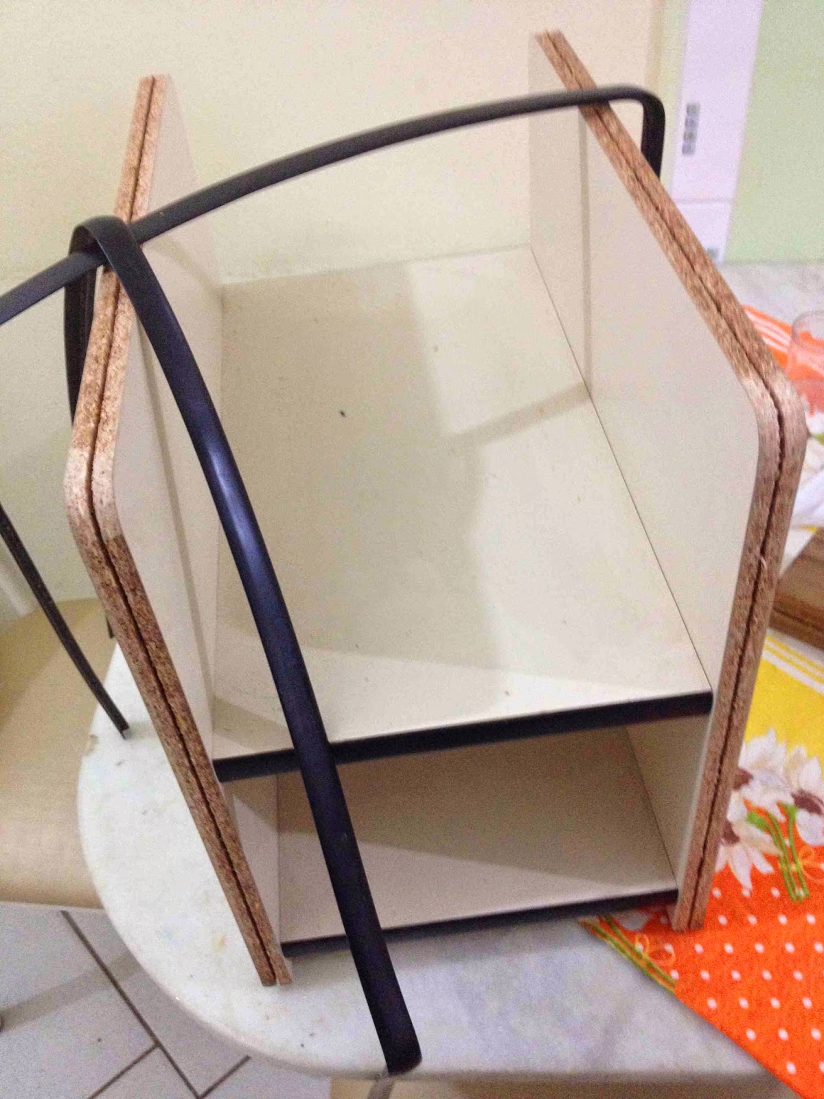
Visando mapear a relação temperatura/resistência, conectamos o mesmo em um multimetro e colocamos o sensor imerso em agua, tomando o cuidado para não curto-circuitar os polos positivo (terminal) e negativo (rosca)  do sensor. Assim apenas a parte da rosca do sensor ficou submersa.

Juntamente com o sensor, foi imerso um termômetro o qual indicará a temperatura da água em um dado instante, podendo relacionar a temperatura indicada, com o valor de resistência medido.


Em verde o multimetro indicando a resistência em kOhm e em vermelho o termômetro indicando a temo em C

Iniciou-se o processo com agua "gelada" a 10C, e elevou-se até a fervura 96C.
A aproximadamente cada 5C de elevação de temperatura, foi medido o valor da resistência, fornecendo um total de 19 pontos medidos.


Temperatura C Resistencia kOhm
10 4
15 3,3
18 3
20 2,8
25 2,2
30 1,7
35 1,35
40 1,15
45 0,9
50 0,75
55 0,65
60 0,5
65 0,45
70 0,35
75 0,3
80 0,25
85 0,2
90 0,18
95 0,15


Ao traçarmos o gráfico que relaciona a temperatura C com a resistência do sensor em kOhm, obtemos uma curva aproximada que não caracteriza bem o comportamento do sensor.

Visando aproximar esta cursa, e com o uso do Matlab, foi calculado um regressão exponencial de 2 ordem, o qual estimou os melhores coeficientes da curva para o sensor.

M = load('sensor.txt');
%Computa regressao exponecial de 2 ordem
%ft=fittype('exp2');
%cf=fit(M(:,2),M(:,1),ft);
% aplica valores lidos:
dados = M(:,2);
%
% General model Exp2:
% cf(x) = a*exp(b*x) + c*exp(d*x)
% Coefficients (with 95% confidence bounds):
% a =       73.89  (67.5, 80.28)
% b =      -5.436  (-6.305, -4.566)
% c =       69.19  (63.08, 75.3)
% d =     -0.4682  (-0.5291, -0.4074)
ptr=1;    
for i=1:22
    result(ptr) = 73.89*exp(-5.436*dados(i)) + 69.19*exp(-0.4682*dados(i));
    ptr=ptr+1;
end
result

Assim, o grafico abaixo ilustra em vermelho, a curva medida, e em azul, a curva aproximada.
(Clique na imagem para aumentar)


A curva em azul informará melhor o valor da temperatura com base na resistência medida, e mapeado conforme equação abaixo:

Temperatura = 73.89*exp(-5.436*Resistencia) + 69.19*exp(-0.4682*Resistencia);

Novos testes ainda são necessários, e quem sabe o fabricante não queira facilitar minha vida :-)


[]'s